After this weekend of test diving I feel that i can conclude my first attempt to make a simple ROV.
Here is a summary of the process: (Links lead to blog posts/photos about each topic)
- I discovered that it was indeed possible to to use small inexpensive pumps for controlling a small underwater craft.
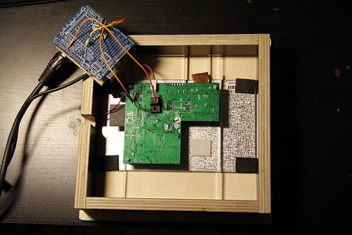
- I found a way to make a watertight camera housing that was easy to assemble, used standard off the shelf parts and no glue of any kind. This allow me to make many copies and scale the design.
- I confirmed that it was possible to use a single CAT5 cable to communicate with the the surface and that the transmission of 240V mains power over this cable could be used in a safe way.
- I tested the ROV several times on land and in the water to develop proper control algorithms.
- Shortly after I was able to dive 8 meters down to explore the bottom.
ROV1 homemade by DZL, from oz2cpu on Vimeo.
Future of the project:
After using several cameras it has become clear that a single fixed focus wide angle camera gives the best result. I plan to hack one of the popular GoPro cameras so it can be remote controlled and provide a live video feed.
The camera will be mounted on a pan/tilt unit inside the ROV for better coverage.
Side thrusters may be installed for side to side control and drift compensation.
Many more posts will appear here over the summer as the project progresses.